Unit 3 – Part B: Optics and Lasers
Q1: Explain the formation of interference fringes in an air-wedge shaped film. How is the thickness of the wire determined by this method?
(i) Formation of Interference Fringes (Air Wedge)
An air wedge is a thin film of air with zero thickness at one end and progressively increasing thickness at the other. This is typically formed by placing a thin object, like a wire, between two optically flat glass plates at one end.
- When monochromatic light (e.g., from a sodium vapour lamp) falls on the wedge-shaped film, it gets partly reflected from the top surface of the air film (Ray 1) and partly transmitted, then reflected from the bottom surface of the air film (Ray 2).
- These two reflected rays (Ray 1 and Ray 2) are coherent, as they originate from the same source.
- A phase change of 180° (or π) occurs for Ray 2, as it reflects from the denser medium (the top surface of the bottom glass plate). No phase shift occurs for Ray 1, which reflects from the rarer medium (the bottom surface of the top glass plate).
- This inherent 180° phase difference between the two rays is the reason they interfere destructively at thepoint of contact (where thickness is zero), forming a dark fringe.
- As the thickness 't' increases, the path difference (2t) also increases, leading to a pattern of alternate bright and dark straight-line fringes.
(ii) Determination of Thickness of Wire
The air wedge setup can be used to measure the thickness (t) of a very small object, like a thin wire.
- Setup: Two optically plane glass plates are placed one over the other. The wire (specimen) is inserted between them at one end, and the other end is tied with a rubber band to form a wedge.
- Illumination: Light from a sodium vapour lamp is made to fall normally on the wedge using a glass sheet held at a 45° angle.
- Observation: The interference fringes are observed through a microscope.
- Measurement: The horizontal positions of several dark fringes (e.g., n, n+5, n+10) are measured. From this, the average width of 5 or 10 fringes is calculated (let's say x = 5β). The fringe width (β) is then found by β = x / 5.
- Calculation: The thickness of the wire (t) is related to the fringe width (β), the wavelength of light (λ), and the length of the air wedge (L) by the formula:
By rearranging this formula, we can determine the thickness of the wire:
Thus, by measuring the fringe width (β) and knowing λ and L, the thickness 't' of the wire can be calculated.
Q2: Describe the construction of a Michelson interferometer and discuss the different type of interference fringes formed in it.
(i) Principle and Construction
Principle: The Michelson Interferometer produces an interference pattern by splitting a beam of light into two parts. These two beams travel different optical paths and are then recombined to interfere. This method is known as "division of amplitude".
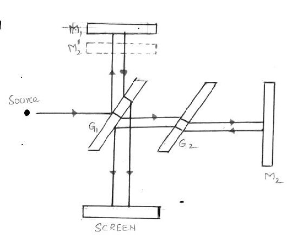
Construction: The main components are:
- Beam Splitter (G1): A glass plate that is semi-silvered or partially polished on its rear side. It is placed at a 45° angle to the incoming light. Its function is to split the source light into two beams of equal intensity: one reflected and one transmitted.
- Compensatory Plate (G2): An identical glass plate placed parallel to G1. It is placed in the path of the transmitted beam to ensure that both beams (the reflected one and the transmitted one) travel through the same thickness of glass.
- Movable Mirror (M1): A highly polished, movable mirror.
- Fixed Mirror (M2): A highly polished, fixed mirror.
- Source: A monochromatic light source.
- Screen: A screen or telescope to observe the interference fringes.
Light from the source hits G1. Part of it is reflected towards M1. The other part is transmitted through G1 and G2 towards M2. The beams reflect from M1 and M2, return to G1, and are recombined to travel towards the screen, where they interfere.
(ii) Types of Fringes
The type of fringe pattern observed depends on the alignment of the mirrors M1 and M2 (which is equivalent to the air film between M1 and the virtual image of M2).
- Circular Fringes: These are observed when the mirrors M1 and M2 are perfectly parallel to each other.
- Curved Fringes: When M1 and M2 are inclined to each other, the air film enclosed is wedge-shaped. This arrangement produces curved fringes.
- Straight Fringes: When the mirrors M1 and M2 are made to intersect, straight-line fringes are obtained.
Q3: Explain the principle, construction, and working of an Nd-YAG laser. List out the advantages and applications of Nd-YAG laser.
The Nd-YAG (Neodymium-doped Yttrium Aluminium Garnet) laser is a four-level, solid-state laser.
(i) Principle
The active medium is an Nd-YAG rod. This rod is optically pumped by a krypton flash tube. The pumping raises the Neodymium ions (Nd3+) to higher energy levels. Population inversion is achieved in a metastable state. The subsequent transition from this metastable state to a lower energy state results in a laser beam of wavelength 1.06 μm.
(ii) Construction
- Active Medium: A cylindrical rod of Yttrium Aluminium Garnet (Y3Al5O12) crystal, in which a small amount of Yttrium ions (Y3+) are replaced by Neodymium ions (Nd3+). The ends of the rod are highly polished and parallel.
- Pumping Source: A krypton flash tube is used for optical pumping.
- Optical Resonator: This consists of two mirrors. One mirror (M1) is fully reflecting, and the other (M2) is partially reflecting. In some designs, the polished ends of the rod itself can act as the resonator.
- Reflector Cavity: The laser rod and flash tube are placed inside an elliptical reflector cavity to ensure that most of the light from the flash tube is focused onto the rod.
(iii) Working
- Pumping: When the krypton flash tube is turned on, it emits light (wavelengths 0.73 μm and 0.80 μm). The Nd3+ ions in the ground state (E0) absorb this energy and are excited to upper energy levels (pump bands E3 and E4).
- Population of Metastable State: From these high-energy pump bands, the Nd3+ ions quickly decay to a lower, metastable state (E2) through a non-radiative transition.
- Population Inversion: Because E2 is a metastable state (long lifetime), ions accumulate here, achieving population inversion between state E2 and a lower state E1.
- Stimulated Emission: An Nd3+ ion makes a spontaneous transition from E2 to E1, emitting a single photon. This photon travels through the rod and triggers other excited ions in state E2 to emit identical photons (stimulated emission).
- Amplification: These photons reflect back and forth between the resonator mirrors (M1 and M2), multiplying rapidly as they cause more stimulated emissions.
- Laser Output: The beam grows in strength until an intense, coherent laser of wavelength 1.06 μm (infra-red) is emitted through the partially reflecting mirror M2. The ions then return from E1 to the ground state E0 via another non-radiative transition.
(iv) Advantages and Applications
Advantages:
- It has a high energy output.
- Population inversion is much easier to achieve (a characteristic of four-level lasers).
Applications:
- Used in range finders and illuminators.
- Widely used in industry for micro-machining operations, such as welding, drilling, resistor trimming, and scribing.
Q4: Explain the modes of vibrations of CO2 molecule. Explain the construction, functioning, and application of CO2 laser with necessary diagrams.
The CO2 laser is a four-level molecular gas laser, one of the most efficient types. Laser transitions occur between the vibrational energy states of the CO2 molecule.
(i) Modes of Vibration of CO2
A CO2 molecule (O-C-O) has three independent modes of vibration:
- Symmetric Stretching: The carbon atom is stationary, while both oxygen atoms vibrate simultaneously along the molecular axis, either moving away from or towards the carbon atom.
- Bending: Both oxygen atoms and the carbon atom vibrate perpendicular to the molecular axis.
- Asymmetric Stretching: The atoms vibrate asymmetrically. The two oxygen atoms move in one direction while the carbon atom moves in the opposite direction, all along the molecular axis.
(ii) Construction
- Active Medium: A gas mixture of Carbon Dioxide (CO2), Nitrogen (N2), and Helium (He).
- Discharge Tube: A long quartz tube (e.g., 5m long, 2.5cm diameter) containing the gas mixture.
- Pumping Source: A high-voltage DC power supply connected to terminals on the discharge tube. This causes an electrical discharge, which is the pumping method.
- Optical Resonator: Formed by two concave mirrors, M1 (fully reflecting) and M2 (partially reflecting), placed at the ends of the tube.
- Brewster Windows: The ends of the tube are fitted with NaCl Brewster windows, which allow the laser light to pass without reflection losses and ensure the output beam is plane-polarized.
(iii) Functioning (Working)
- Pumping (Nitrogen): The electrical discharge excites electrons. These high-energy electrons collide with Nitrogen molecules (N2), exciting them to a metastable vibrational state.
N2 + e* → N2* + e
- Energy Transfer (Population Inversion): The excited state of N2 (N2*) is very close in energy to the E5 (asymmetric stretching) state of the CO2 molecule. Through collisions, the energy is efficiently transferred from the excited N2 to the CO2 molecules.
N2* + CO2 → CO2* + N2This process populates the E5 level of CO2, achieving population inversion relative to lower levels E4 and E3.
- Laser Transitions (Stimulated Emission): Laser action occurs in two main transitions:
- E5 → E4 (Symmetric Stretching): This transition is more intense and produces a laser beam of wavelength 10.6 μm.
- E5 → E3 (Bending): This transition produces a laser beam of wavelength 9.6 μm.
- Role of Helium: Helium is not directly involved in the lasing action. Its role is to conduct heat from the center of the discharge tube to the cool walls, maintaining the efficiency of the laser.
(iv) Applications
- Industrial (Material Processing): Due to its high power, it is used for welding, drilling, cutting, and soldering.
- Surgical: Widely used in neurosurgery, general surgery, and microsurgery. It acts as a "bloodless" surgical knife.
- Medical Treatment: Used in the treatment of liver and lung diseases.
- Communications: Suitable for open-air communication due to low atmospheric attenuation at its wavelength.
- Sensing: Used in remote sensing.
Q5: With proper theory and diagrams, derive Einstein’s coefficients. Also discuss its inferences.
(i) Theory: Interaction of Radiation with Matter
When radiation interacts with matter, three processes can occur. Consider an atom with two energy levels, a lower ground state E1 (population N1) and a higher excited state E2 (population N2). The energy density of the incident radiation is Q.
- Stimulated Absorption: An atom in the ground state (E1) absorbs an incident photon of energy hv = E2 - E1 and jumps to the excited state (E2). The rate of absorption (Nab) is proportional to the ground state population (N1) and the radiation energy density (Q).
Nab = B12 N1 QWhere B12 is the Einstein's coefficient of stimulated absorption.
- Spontaneous Emission: An atom in the excited state (E2) returns to the ground state (E1) by itself, emitting a photon of energy hv. This process is independent of the external radiation field. The rate (Nsp) is proportional to the excited state population (N2).
Nsp = A21 N2Where A21 is the Einstein's coefficient for spontaneous emission.
- Stimulated Emission: An incident photon of energy hv triggers (or induces) an atom in the excited state (E2) to return to the ground state (E1). This process emits a *second* photon that is identical in energy, phase, and direction to the incident photon. The rate (Nst) is proportional to the excited state population (N2) and the radiation energy density (Q).
Nst = B21 N2 QWhere B21 is the Einstein's coefficient for stimulated emission.
(ii) Derivation of Einstein's Coefficients
At thermal equilibrium (steady state), the total rate of upward transitions (absorption) must equal the total rate of downward transitions (spontaneous + stimulated emission).
Nab = Nsp + Nst
B12 N1 Q = A21 N2 + B21 N2 Q
Now, we solve for the energy density Q:
Q (B12 N1 - B21 N2) = A21 N2
Q = (A21 N2) / (B12 N1 - B21 N2)
Divide the numerator and denominator by B21 N2:
From Boltzmann's distribution law, the ratio of populations at thermal equilibrium is:
Substituting this into the equation for Q:
We compare this expression with Planck's radiation formula for energy density of a black body:
By comparing equations (1) and (2), we get the relations between the Einstein's coefficients:
- (B12/B21) = 1 or B12 = B21
- (A21/B21) = 8πhν3/c3
(iii) Inferences (Conclusions)
- The probability of stimulated absorption (B12) is equal to the probability of stimulated emission (B21).
- The ratio of spontaneous emission to stimulated emission (A21/B21) is proportional to ν3 (the cube of the radiation frequency).
- This means that as the energy difference (hv) between the two states increases, spontaneous emission becomes much more dominant than stimulated emission. This is why it is difficult to achieve laser action (which requires dominant stimulated emission) at very high frequencies (e.g., X-rays).
Q6: Derive an expression for numerical aperture and acceptance angle of an optical fiber.
(i) Principle
The propagation of light through an optical fiber is based on the principle of Total Internal Reflection (TIR). An optical fiber consists of a central Core (refractive index n1) surrounded by a Cladding (refractive index n2), where n1 > n2.
For TIR to occur, light must travel from the denser medium (core) to the rarer medium (cladding). If the angle of incidence at the core-cladding interface is greater than the critical angle (φc), the light ray is completely reflected back into the core and propagates along the fiber.
(ii) Definitions
- Acceptance Angle (θ0): The maximum angle of incidence at the fiber end (in the launching medium, n0) for which the light ray can enter the fiber and still undergo total internal reflection.
- Numerical Aperture (NA): The sine of the acceptance angle (NA = sin θ0). It represents the light-gathering ability of the fiber.
(iii) Derivation
Consider a light ray entering the fiber from a launching medium (refractive index n0) at the maximum acceptance angle θ0.
- At the Fiber End (Point A): The ray refracts into the core (n1) at an angle θr. Applying Snell's Law at this interface:
n0 sin θ0 = n1 sin θr ------- (1)
- At the Core-Cladding Interface (Point B): The ray strikes the interface at an angle φ. From the geometry of the right triangle (ΔABC), we can see that:
φ = 90° - θrFor the ray to be *just* totally internally reflected (i.e., for θ0 to be the *maximum* acceptance angle), the angle of incidence φ must be exactly equal to the critical angle φc. At the critical angle, the ray is refracted at 90° into the cladding (n2).
Applying Snell's Law at Point B:n1 sin φc = n2 sin 90°
n1 sin(90° - θr) = n2 (1)
n1 cos θr = n2
cos θr = n2/n1 ------- (2) - Combining the Equations: We use the trigonometric identity sin2θr + cos2θr = 1, which gives sin θr = √(1 - cos2θr).
Substitute Eq. (2) into this identity:sin θr = √(1 - (n2/n1)2) = √((n12 - n22) / n12)Now, substitute this expression for sin θr back into Eq. (1):n0 sin θ0 = n1 [ √((n12 - n22) / n12) ]
n0 sin θ0 = n1 [ √(n12 - n22) / n1 ]
n0 sin θ0 = √(n12 - n22)
(iv) Final Expressions
Numerical Aperture (NA):
By definition, NA = sin θ0. Therefore:
If the medium surrounding the fiber is air, n0 = 1. The formula simplifies to:
Acceptance Angle (θ0):
From the NA expression, we find the acceptance angle:
θ0 = sin-1( √(n12 - n22) / n0 )
If the surrounding medium is air (n0 = 1):