Part B: Energy Sources and Storage Devices
1. i) How is wind energy harnessed? What are its advantages and limitations? ii) Write a detailed note on Breeder reactor.
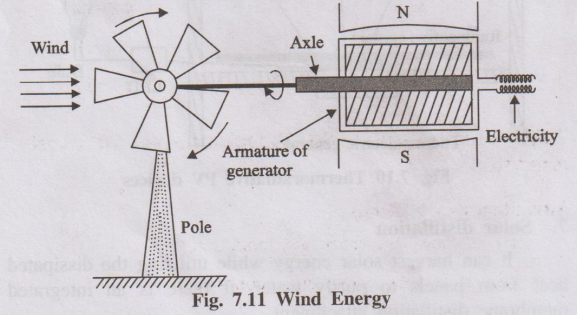
i) Wind Energy Harnessing, Advantages, and Limitations
Harnessing Wind Energy:
- Wind Turbines: Wind energy is captured using large wind turbines. These turbines have large blades (usually 2 or 3) mounted on a tall tower.
- Kinetic to Mechanical Energy: The kinetic energy of the moving air (wind) pushes against the blades, causing them to rotate.
- Mechanical to Electrical Energy: The rotating blades turn a shaft connected through a gearbox (to increase rotational speed) to a generator located in the nacelle (the housing at the top of the tower).
- Generation: The generator converts the mechanical rotational energy into electrical energy.
- Transmission: The electricity generated is then conditioned (voltage stepped up) and transmitted through power lines to the grid or used locally.
Advantages:
- Renewable & Clean: Wind is an inexhaustible resource, and wind power generation produces no greenhouse gas emissions or air/water pollution during operation.
- Low Operating Costs: After installation, fuel costs are zero, and operating/maintenance costs are relatively low.
- Land Use Efficiency: Wind farms can often coexist with agricultural or other land uses.
- Energy Independence: Reduces reliance on imported fossil fuels.
Limitations:
- Intermittency: Wind speed varies, so power generation is not constant and requires backup power sources or energy storage.
- Visual and Noise Impact: Some people find wind turbines aesthetically displeasing, and they can generate noise.
- Wildlife Impact: Turbines can pose a risk to birds and bats if not sited carefully.
- Location Dependent: Requires locations with consistent and adequate wind speeds, which are often remote.
- High Initial Cost: Manufacturing and installing wind turbines requires significant capital investment.
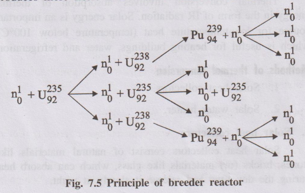
ii) Breeder Reactor
A breeder reactor is a nuclear reactor designed to produce more fissile material (nuclear fuel) than it consumes while generating power.
Principle:
- It primarily uses fast neutrons (neutrons that have not been slowed down by a moderator) to sustain the fission chain reaction.
- While fission occurs in fissile isotopes (like Plutonium-239 or Uranium-235), surplus fast neutrons are captured by fertile isotopes (like Uranium-238, which makes up >99% of natural uranium).
- This neutron capture converts the fertile isotope into a new fissile isotope. For example:
\( ^{238}_{92}U + ^1_0n \rightarrow ^{239}_{92}U \xrightarrow{\beta^-} ^{239}_{93}Np \xrightarrow{\beta^-} ^{239}_{94}Pu \)Here, fertile Uranium-238 is converted into fissile Plutonium-239.
Key Features:
- Fuel Cycle: Typically uses a fuel mixture containing Plutonium (Pu) bred from previous cycles and fertile Uranium-238.
- No Moderator: Uses fast neutrons, so moderators like water are generally avoided.
- Coolant: Requires coolants that do not significantly slow down neutrons, such as liquid metals (e.g., liquid sodium) or gas (e.g., helium). Liquid sodium is common but poses safety challenges due to its reactivity.
- Breeding Ratio: The ratio of fissile material produced to fissile material consumed. In a breeder reactor, this ratio is greater than 1.
Significance:
- Resource Utilization: Greatly increases the energy obtainable from uranium resources by utilizing the abundant Uranium-238 isotope, potentially extending nuclear fuel supplies for centuries.
- Waste Management: Can potentially burn some long-lived radioactive waste products (actinides).
Challenges: Include the complexity of handling fast neutrons and liquid metal coolants, higher costs, and proliferation concerns associated with plutonium.
2. i) Describe the construction and working of Hydrogen Oxygen fuel cell. ii) Describe the construction and working of microbial fuel cell
i) Hydrogen-Oxygen (H2-O2) Fuel Cell
This is one of the simplest and most common types of fuel cells, often using a Proton Exchange Membrane (PEM).
Construction:
- Electrodes: Two porous electrodes (anode and cathode) typically made of carbon coated with a platinum catalyst.
- Electrolyte: A solid polymer membrane (Proton Exchange Membrane or PEM) sandwiched between the electrodes. This membrane only allows protons (H+) to pass through.
- Gas Flow Channels: Channels are machined into plates backing the electrodes to distribute hydrogen gas to the anode and oxygen (or air) to the cathode.
- External Circuit: Connects the anode and cathode, allowing electrons to flow and do work (generate electricity).
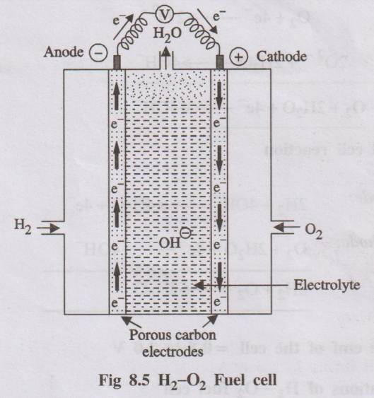
Working:
- Anode Reaction: Hydrogen gas is fed to the anode. The platinum catalyst splits H2 molecules into protons (H+) and electrons (e-).
Anode: \( H_2 \rightarrow 2H^+ + 2e^- \)
- Proton Transport: The protons (H+) migrate through the PEM electrolyte towards the cathode.
- Electron Flow: The electrons (e-) cannot pass through the PEM. They travel through the external circuit, generating an electric current.
- Cathode Reaction: Oxygen (from air) is fed to the cathode. It reacts with the protons arriving through the PEM and the electrons arriving through the external circuit, catalyzed by platinum, to form water.
Cathode: \( \frac{1}{2}O_2 + 2H^+ + 2e^- \rightarrow H_2O \)
- Overall Reaction: The net reaction is the combination of hydrogen and oxygen to produce water and electricity.
Overall: \( H_2 + \frac{1}{2}O_2 \rightarrow H_2O + \text{Electrical Energy} + \text{Heat} \)
Advantages: High efficiency, zero emissions (only water byproduct), quiet operation.
Disadvantages: Cost of catalysts (platinum), hydrogen production and storage challenges.
ii) Microbial Fuel Cell (MFC)
An MFC uses microorganisms (bacteria) as biocatalysts to convert chemical energy stored in organic matter directly into electricity.
Construction:
- Anode Chamber: An anaerobic (oxygen-free) compartment containing the anode electrode and electrochemically active bacteria (electrogens) suspended in a solution containing organic fuel (e.g., wastewater, glucose).
- Cathode Chamber: A compartment containing the cathode electrode, typically exposed to oxygen (air).
- Separato /Membrane: Often a Proton Exchange Membrane (PEM) or a salt bridge separating the anode and cathode chambers, allowing protons (H+) generated at the anode to pass to the cathode while preventing oxygen diffusion into the anode chamber.
- Electrodes: Typically made of carbon-based materials (graphite felt, carbon cloth) to support bacterial biofilm growth (anode) and facilitate oxygen reduction (cathode, sometimes catalyzed).
- External Circuit: Connects the anode and cathode for electron flow.
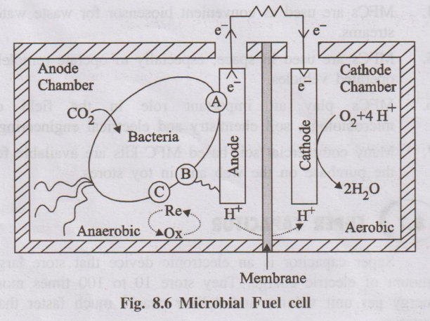
Working:
- Anode Reaction (Bio-oxidation): Electrogenic bacteria colonize the anode surface. They metabolize (oxidize) organic compounds (fuel) present in the anolyte (e.g., acetate CH3COO-). During this process, they release electrons (e-), protons (H+), and carbon dioxide (CO2). The electrons are transferred directly or indirectly to the anode electrode.
Anode (example with acetate): \( CH_3COO^- + 2H_2O \xrightarrow{\text{Bacteria}} 2CO_2 + 7H^+ + 8e^- \)
- Electron Flow: Electrons travel from the anode through the external circuit to the cathode, generating electricity.
- Proton Transport: Protons (H+) migrate from the anode chamber through the separator/membrane to the cathode chamber.
- Cathode Reaction (Reduction): At the cathode, electrons arriving from the external circuit and protons arriving through the membrane react with an electron acceptor, typically oxygen from the air, to form water.
Cathode (with oxygen): \( O_2 + 4H^+ + 4e^- \rightarrow 2H_2O \)
Applications: Wastewater treatment (simultaneously cleaning water and generating power), biosensors, power sources for remote low-power devices.
Challenges: Low power output, cost, long-term stability.
3. What is photovoltaic cell? Explain the construction and working of a photovoltaic cell with a diagram.
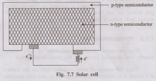
A photovoltaic (PV) cell, commonly known as a solar cell, is a semiconductor device that converts light energy (photons), typically from the sun, directly into electricity (voltage and current) through the photovoltaic effect.
Construction:
Most common PV cells are based on silicon (Si):
- Semiconductor Layers: The core is a p-n junction formed by joining two layers of semiconductor material, usually silicon.
- n-type layer: Silicon doped with an element like phosphorus, creating an excess of free electrons (negative charge carriers). This is typically the top layer.
- p-type layer: Silicon doped with an element like boron, creating an abundance of "holes" (absence of electrons, acting as positive charge carriers). This is typically the bottom layer.
- p-n Junction: The interface between the n-type and p-type layers. An intrinsic electric field is established across this junction due to the diffusion of charge carriers.
- Metal Contacts:
- Front Contact: A metallic grid (thin fingers and wider busbars, often silver) on the top (sun-facing) n-type surface allows light to enter while collecting electrons.
- Back Contact: A full metallic layer (often aluminum) on the bottom p-type surface collects holes.
- Anti-reflective Coating: A thin layer (like silicon nitride) applied to the top surface to minimize light reflection and maximize light absorption into the silicon.
- Encapsulation: The cell is usually encapsulated (e.g., with glass on top and a backsheet) for protection against moisture and physical damage.
Working (Photovoltaic Effect):
- Light Absorption: When photons (light particles) with sufficient energy strike the silicon material, they are absorbed.
- Electron-Hole Pair Generation: This absorbed energy excites electrons from the valence band to the conduction band, leaving behind a hole in the valence band. This creates mobile electron-hole pairs.
- Charge Separation: The built-in electric field at the p-n junction separates these generated electron-hole pairs. Electrons are swept towards the n-type layer, and holes are swept towards the p-type layer. This prevents them from immediately recombining.
- Current Generation: If an external circuit is connected between the front and back metal contacts, the separated electrons flow out of the n-type layer, through the circuit (doing work, e.g., lighting a bulb), and back into the p-type layer to recombine with holes. This flow of electrons constitutes an electric current (Direct Current - DC).
- Voltage Development: The separation of charges by the p-n junction creates a voltage difference (potential) across the cell.
In summary, the PV cell uses the energy from photons to create charge carriers (electrons and holes), separates them using the p-n junction's electric field, and drives the electrons through an external circuit to produce electricity.
4. i) Explain the construction and working of Lead acid storage battery. ii) Working mechanism of lithium ion battery with neat diagram
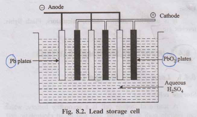
i) Lead-Acid Storage Battery
A lead-acid battery is a common type of secondary (rechargeable) battery used extensively in automobiles.
Construction:
- Electrodes: Consists of multiple plates arranged alternately.
- Negative Plates: Grids made of a lead alloy filled with spongy lead (Pb).
- Positive Plates: Grids made of a lead alloy filled with lead dioxide (PbO2).
- Separators: Thin, porous, insulating sheets (e.g., rubber, PVC) placed between positive and negative plates to prevent short circuits while allowing ion flow.
- Electrolyte: An aqueous solution of sulfuric acid (H2SO4), typically around 35-40% concentration by weight.
- Container: A robust, acid-resistant container (usually polypropylene) housing the plates and electrolyte, often divided into multiple cells (each cell providing ~2V). A 12V car battery typically has 6 cells connected in series.
- Terminals: Heavy lead terminals connect the cells in series and provide connection points for the external circuit.
Working (Discharging):
When the battery supplies current:
- At the Negative Electrode (Anode): Spongy lead (Pb) reacts with sulfate ions (SO42-) from the electrolyte to form lead sulfate (PbSO4) and release electrons.
Anode: \( Pb(s) + SO_4^{2-}(aq) \rightarrow PbSO_4(s) + 2e^- \)
- At the Positive Electrode (Cathode): Lead dioxide (PbO2) reacts with hydrogen ions (H+) and sulfate ions (SO42-) from the electrolyte, consuming electrons to form lead sulfate (PbSO4) and water (H2O).
Cathode: \( PbO_2(s) + 4H^+(aq) + SO_4^{2-}(aq) + 2e^- \rightarrow PbSO_4(s) + 2H_2O(l) \)
- Overall Reaction: Lead and lead dioxide are converted to lead sulfate, consuming sulfuric acid and producing water and electrical energy.
Overall (Discharge): \( Pb(s) + PbO_2(s) + 2H_2SO_4(aq) \rightarrow 2PbSO_4(s) + 2H_2O(l) \)
- As the battery discharges, both electrodes become coated with lead sulfate, and the sulfuric acid concentration decreases.
Working (Charging):
When an external voltage is applied, the reactions reverse:
- At the Negative Electrode (Cathode during charging): Lead sulfate is converted back to spongy lead.
\( PbSO_4(s) + 2e^- \rightarrow Pb(s) + SO_4^{2-}(aq) \)
- At the Positive Electrode (Anode during charging): Lead sulfate is converted back to lead dioxide.
\( PbSO_4(s) + 2H_2O(l) \rightarrow PbO_2(s) + 4H^+(aq) + SO_4^{2-}(aq) + 2e^- \)
- Overall Reaction (Charging): Lead sulfate and water are converted back to lead, lead dioxide, and sulfuric acid, restoring the battery's charge.
Overall (Charge): \( 2PbSO_4(s) + 2H_2O(l) \rightarrow Pb(s) + PbO_2(s) + 2H_2SO_4(aq) \)
ii) Lithium-Ion Battery
Lithium-ion (Li-ion) batteries are secondary batteries widely used in portable electronics and EVs due to their high energy density.
Construction:
- Negative Electrode (Anode): Typically made of graphite (carbon) which can intercalate (store) lithium ions within its layered structure. Usually coated on a copper foil current collector.
- Positive Electrode (Cathode): Typically a metal oxide containing lithium, such as Lithium Cobalt Oxide (LiCoO2), Lithium Manganese Oxide (LiMn2O4), or Lithium Iron Phosphate (LiFePO4). Usually coated on an aluminum foil current collector.
- Electrolyte: A non-aqueous liquid organic solvent (e.g., ethylene carbonate, dimethyl carbonate) containing a dissolved lithium salt (e.g., LiPF6), which allows lithium ions (Li+) to move between the electrodes.
- Separator: A thin, porous polymer membrane placed between the anode and cathode. It prevents electrical short circuits but allows lithium ions to pass through.
- Casing: A metal or polymer casing enclosing the components.
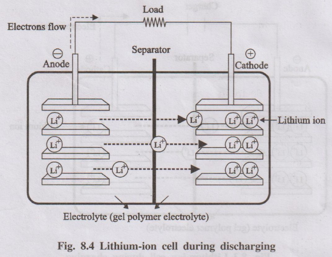
Working Mechanism (Discharging - Battery powering a device):
- Anode (Oxidation): Lithium atoms stored within the graphite structure lose an electron (become Li+ ions) and de-intercalate (move out) from the graphite.
Anode: \( Li_x C_6 \rightarrow xLi^+ + x e^- + C_6 \)
- Electron Flow: The released electrons travel through the external circuit, providing electrical current to the device.
- Ion Movement: The Li+ ions move from the anode, through the electrolyte and separator, towards the cathode.
- Cathode (Reduction): Li+ ions arriving at the cathode intercalate (insert themselves) into the crystal structure of the metal oxide cathode material, while electrons arrive from the external circuit to maintain charge balance (reducing the transition metal in the oxide).
Cathode (example with LiCoO2): \( CoO_2 + xLi^+ + x e^- \rightarrow Li_x CoO_2 \)
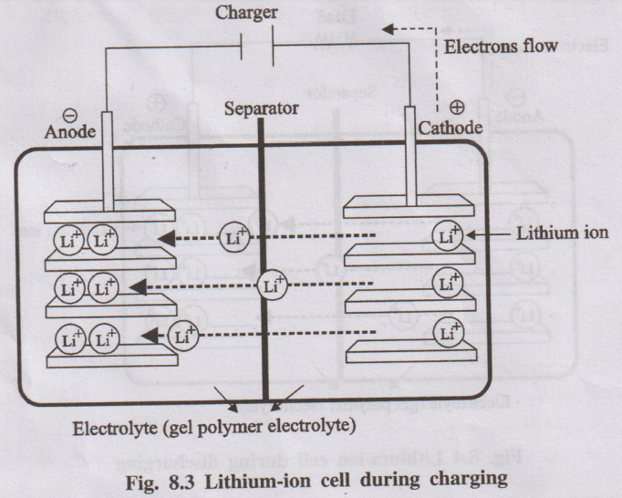
Working Mechanism (Charging - Battery being recharged):
The process is reversed by applying an external voltage:
- Cathode (Oxidation): Lithium ions de-intercalate from the cathode material, releasing electrons.
- Electron Flow: Electrons are forced through the external circuit back to the anode by the charger.
- Ion Movement: Li+ ions move from the cathode, through the electrolyte and separator, towards the anode.
- Anode (Reduction): Li+ ions intercalate back into the graphite structure at the anode, combining with the electrons arriving from the circuit.
Essentially, charging moves lithium ions from the cathode to the anode, and discharging moves them back from the anode to the cathode, with electrons flowing through the external circuit.
5. Explain the components, working and types of E-vehicles in detail.
Components of Electric Vehicles (EVs):
Key components differ from traditional internal combustion engine (ICE) vehicles:
- Traction Battery Pack: The main energy storage system, typically a large lithium-ion battery pack, providing high voltage DC power.
- Electric Traction Motor: Uses electricity from the battery to generate torque and drive the wheels. EVs can have one or more motors.
- Power Electronics Controller / Inverter: Converts the DC power from the battery into AC power (usually) required by the traction motor and controls the motor's speed and torque based on accelerator input.
- Onboard Charger: Converts AC power from the grid (when plugged in) into DC power to charge the traction battery.
- Charging Port: The external interface for plugging in a charger to replenish the battery.
- DC-DC Converter: Steps down the high voltage from the traction battery to lower voltage DC power needed for auxiliary systems (lights, wipers, infotainment, etc.) and to charge the auxiliary 12V battery.
- Auxiliary Battery: A standard 12V battery (often lead-acid or Li-ion) powering standard vehicle accessories.
- Transmission: EVs often have a simpler, single-speed or two-speed transmission compared to multi-gear transmissions in ICE cars, as electric motors provide high torque over a wide speed range.
- Thermal Management System: Cools or heats the battery pack and power electronics to maintain optimal operating temperatures for performance and longevity.
Working of EVs:
- Charging: The onboard charger takes AC power from the grid via the charging port and converts it to DC power to charge the main traction battery.
- Power Delivery: When the accelerator pedal is pressed, the power electronics controller draws DC power from the traction battery.
- Inversion: The inverter converts this DC power to controlled AC power (varying frequency and voltage).
- Motor Operation: The AC power drives the electric traction motor(s), generating torque.
- Driving Wheels: The torque is transferred through the transmission (if present) and driveshafts to rotate the wheels, propelling the vehicle.
- Regenerative Braking: When decelerating or braking, the controller can operate the traction motor as a generator. It converts the vehicle's kinetic energy back into electricity, which is sent back to recharge the traction battery slightly, improving efficiency.
- Auxiliary Power: The DC-DC converter continuously supplies power to the 12V auxiliary systems.
Types of E-Vehicles:
- Battery Electric Vehicles (BEVs):
- Powered solely by electricity stored in the traction battery pack.
- Have no internal combustion engine, fuel tank, or exhaust system.
- Charged by plugging into an external power source.
- Produce zero tailpipe emissions.
- Examples: Tesla Model 3, Nissan Leaf, Tata Nexon EV.
- Hybrid Electric Vehicles (HEVs):
- Combine an internal combustion engine (ICE) with an electric motor and a relatively small battery pack.
- The battery is charged primarily by the ICE and regenerative braking (cannot be plugged in).
- Can run on the electric motor alone at low speeds, the ICE alone, or both combined for better fuel efficiency than conventional cars.
- Examples: Toyota Prius, Honda Civic Hybrid.
- Plug-in Hybrid Electric Vehicles (PHEVs):
- Similar to HEVs but have a larger battery pack that *can* be charged by plugging into an external power source.
- Can travel a significant distance (e.g., 20-50 miles) on electricity alone before the ICE needs to turn on.
- Offer electric driving for short trips and hybrid operation for longer journeys.
- Examples: Chevrolet Volt (discontinued), Toyota Prius Prime, BMW 330e.
- Fuel Cell Electric Vehicles (FCEVs):
- Use a fuel cell (typically hydrogen-oxygen) to generate electricity onboard, which then powers an electric motor similar to a BEV.
- Have a hydrogen tank instead of a large battery pack (though usually include a smaller buffer battery).
- Produce only water vapor as emissions.
- Refueling with hydrogen is relatively fast, similar to gasoline cars.
- Challenges include the high cost of fuel cells and the limited hydrogen refueling infrastructure.
- Examples: Toyota Mirai, Hyundai Nexo.
6. Explain the various components of light water nuclear reactor with a block diagram with its parts and functions
A Light Water Reactor (LWR) is the most common type of nuclear power reactor, using ordinary water (H2O) as both the coolant and the neutron moderator.
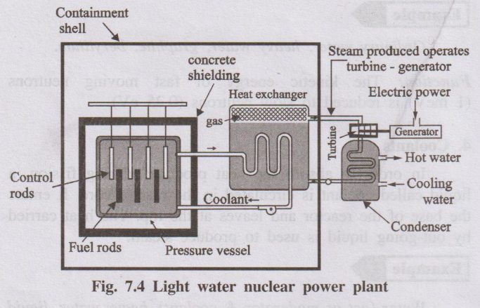
Components and Functions:
- Reactor Core:
- Function: The heart of the reactor where nuclear fission occurs and heat is generated.
- Contains:
- Fuel Assemblies: Bundles of long metal tubes (cladding, usually zirconium alloy) containing pellets of nuclear fuel (typically enriched Uranium Oxide, UO2).
- Moderator: Light water (H2O) fills the core, surrounding the fuel assemblies. It slows down fast neutrons produced by fission to thermal energies, making further fission more likely.
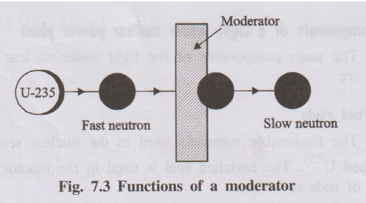
- Control Rods: Rods made of neutron-absorbing material (e.g., cadmium, boron, hafnium). They are inserted into or withdrawn from the core to control the rate of fission and thus the reactor's power level. Inserting them absorbs neutrons and slows the reaction; withdrawing them speeds it up. Used for startup, shutdown, and power adjustments.
- Coolant:
- Function: Removes the intense heat generated by fission in the core and transfers it to generate steam. In an LWR, the coolant is also the light water moderator.
- Flow: Water is pumped through the reactor core, absorbing heat.
- Reactor Pressure Vessel (RPV):
- Function: A large, thick-walled steel container that houses the reactor core, moderator, coolant, and core support structures. It withstands the high pressures and temperatures of the reactor coolant.
- Steam Generator (in Pressurized Water Reactors - PWRs):
- Function: A heat exchanger where the very hot, high-pressure primary coolant water from the reactor core flows through tubes. Heat is transferred to a separate loop of secondary water (also light water) outside the tubes, causing it to boil and produce steam. This keeps the radioactive primary coolant contained.
- (In Boiling Water Reactors - BWRs, steam is generated directly within the reactor pressure vessel).
- Steam Turbine:
- Function: High-pressure steam (from the steam generator in a PWR or the reactor vessel in a BWR) is directed onto the blades of a turbine, causing it to rotate rapidly. Converts thermal energy (steam) into mechanical energy.
- Electric Generator (Alternator):
- Function: Connected to the rotating turbine shaft. It converts the mechanical energy of the turbine's rotation into electrical energy.
- Condenser:
- Function: Cools the low-pressure steam exiting the turbine using a large flow of cooling water (from a river, lake, or cooling tower), condensing it back into liquid water. This maintains a pressure difference across the turbine, maximizing efficiency.
- Containment Building:
- Function: A large, robust structure (often steel-lined reinforced concrete) enclosing the reactor pressure vessel and primary coolant system. Designed to contain radioactive materials in case of an accident and protect the reactor from external hazards.
- Pumps: Circulate the primary coolant through the reactor and steam generator (PWR), and circulate feed water back to the steam generator (PWR) or reactor vessel (BWR) after it passes through the condenser.
7. Give the detailed description about the recent development in the solar cell material
While crystalline silicon (c-Si) remains the dominant material in the solar cell market due to its maturity, efficiency, and decreasing cost, significant recent developments focus on alternative and advanced materials aiming for lower costs, higher efficiencies, flexibility, and new applications.
Key Developments:
- Perovskite Solar Cells (PSCs):
- Material: Based on materials with a specific crystal structure similar to calcium titanate (perovskite), typically hybrid organic-inorganic lead or tin halide-based materials (e.g., methylammonium lead iodide - MAPbI3).
- Advantages: Rapid increase in lab efficiencies (rivaling silicon), potentially very low manufacturing costs (solution-processable, printable), tunable bandgaps, lightweight and potentially flexible.
- Challenges: Long-term stability (degradation due to moisture, oxygen, heat, light), toxicity of lead (research ongoing into lead-free alternatives), scalability of high-performance devices.
- Recent Focus: Improving stability through compositional engineering, interface passivation, encapsulation techniques; developing lead-free compositions; scaling up manufacturing.
- Tandem/Multi-junction Solar Cells:
- Concept: Stacking multiple solar cell layers (junctions), each optimized to absorb a different part of the solar spectrum more efficiently. This overcomes the theoretical efficiency limit (Shockley-Queisser limit) of single-junction cells.
- Materials Combinations:
- Perovskite-Silicon Tandems: A major focus area. A wider-bandgap perovskite top cell absorbs high-energy (blue/green) light efficiently, while the silicon bottom cell absorbs lower-energy (red/infrared) light passing through. Efficiencies exceeding 30% have been demonstrated, potentially offering higher performance than silicon alone at slightly increased cost.
- III-V Multi-junctions: Based on materials like Gallium Arsenide (GaAs), Indium Gallium Phosphide (InGaP), etc. Hold the record for highest efficiencies (>45%) but are very expensive, primarily used in space applications and concentrator PV. Research aims to reduce their cost.
- Challenges: Complex manufacturing, current matching between layers, long-term stability of perovskite layers in tandems.
- Organic Photovoltaics (OPVs):
- Material: Based on carbon-based organic polymers or small molecules as the light-absorbing active layer.
- Advantages: Potentially very low cost, lightweight, flexible, semi-transparent, printable using roll-to-roll techniques.
- Challenges: Lower efficiencies compared to silicon and perovskites, limited operational lifetime (degradation).
- Recent Focus: Development of new non-fullerene acceptor materials leading to significant efficiency improvements (approaching 20% in labs), improving device stability and lifetime.
- Quantum Dot Solar Cells (QDSCs):
- Material: Use semiconductor nanocrystals (quantum dots) as the light-absorbing material.
- Advantages: Tunable bandgap (by changing dot size) allowing absorption optimization, potential for high efficiency via effects like multiple exciton generation (MEG), solution processability.
- Challenges: Efficiency improvements needed, stability issues, toxicity concerns (e.g., Cadmium-based QDs, though alternatives exist).
- Thin-Film Technologies (CIGS, CdTe):
- Material: Copper Indium Gallium Selenide (CIGS) and Cadmium Telluride (CdTe) are established thin-film materials.
- Advantages: Lower material usage than silicon, good performance, potential for flexible substrates.
- Recent Focus: Continued efforts to improve efficiency, reduce manufacturing costs, address material supply/toxicity concerns (Cadmium in CdTe, Indium/Gallium scarcity for CIGS).
Overall, the trend is towards higher efficiencies (especially via tandem structures), lower manufacturing costs (solution processing, printing), improved stability and lifetime, and exploring materials suitable for flexible and niche applications beyond traditional rigid panels.